By Andrew Corney ZL2BBJ
Perhaps the most challenging task in converting the antennas at Quartz Hill from receive-only to transmit-and-receive was finding low-cost transmitting baluns to replace the low power receive baluns. The antennas and 600 ohm open-wire transmission lines are extremely rugged in order to survive the high winds at the site, and could easily handle tens of kilowatts even though they were only used for reception. The 600 ohm lines from the antennas terminate on gantries near the station building, and 600 to 50 ohm baluns were used to connect the 600 ohm lines to underground coaxial cables running from the gantries to the building. Up to 10 baluns capable of handling the legal power limit over sustained contest operation were required to replace the original receive-only baluns, which would have handled 10 watts at most. Commercial baluns would have been prohibitively expensive, so the home-brew option was investigated. Initial findings were not encouraging. Moxon [1] confesses to failed attempts to make a 600:50 ohm balun, and suggests using 200:50 ohm baluns instead, and putting up with the SWR, but this was not an option for Quartz Hill. Sevick [2] describes a 600:50 ohm balun which uses two toroid cores and has a frequency range limited to 7 to 30 MHz. The solution to the balun problem came when we were loaned a surplus commercial 100 W balun to "reverse engineer". Its design proved to be simple, but rather subtle. The design was copied, but the power rating was scaled up to permit sustained contest operation without fear of over-heating.
For higher ratios, a transformer balun is simpler than the transmission line types popular for lower impedance ratios, but a few tricks are needed to get good results. The choice of the correct type of toroid core is absolutely critical. The windings must be arranged to get the best compromise between maximising inductive coupling and minimising inter-winding capacitance. And finally, the primary is fed by a series capacitor which gives a low-Q resonance at the lowest frequency of operation, enabling operation at the lowest frequency with fewer turns than would otherwise be needed, which greatly extends the highest frequency of operation.
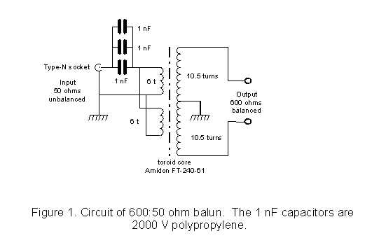
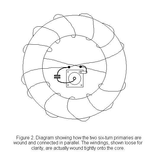
The circuit of the balun is given in Fig. 1. The toroid core is an Amidon type FT-240-61. Cores by other manufactures can be used provided they are of an equivalent type of ferrite. Other types of ferrite, or the iron-dust cores sometimes used for baluns, will not work. The primary comprises two six-turn windings of 1.2 mm diameter (18 swg) enameled copper wire connected in parallel. Each six-turn primary winding has its turns spaced evenly over half the toroid circumference, and the two windings are connected in parallel, Fig. 2, taking particular care to get the phasing correct. One end of the paralleled primaries goes to the outer of a type-N 50 ohm socket, while the other end is connected to the inner of the socket via the 3 nF series capacitor. The 3 nF capacitor comprises three paralleled 1000 pF 2000 V polypropylene capacitors, (a number of these capacitors had been obtained as surplus). A single 3,300 pF 500 V silver-mica "dogbone" capacitor would be equally suitable.


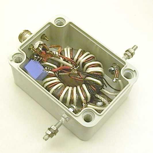
The secondary winding is 21 turns evenly spaced around the whole circumference of the toroid. The secondary is tapped at the centre, with 10.5 turns on either side. The centre tap is connected to the earthed end of the primary at the outer of the type-N socket. The wire used for the secondary is critical. The commercial balun which was copied used quite fine stranded wire with PTFE insulation, but using similar wire for the larger balun gave a poor SWR above 20 MHz. Very good results were obtained when the PTFE insulated wire was replaced with foam dielectric insulated stranded inner conductor stripped from 75 ohm, 4.5 mm external diameter coaxial cable. This cable was surplus and of unknown type, but is believed to be similar to UR202. The secondary is wound tightly over the primary, and held in place with nylon lacing cord. The inner from a similar sized 75 ohm cable with solid polythene dielectric would be more difficult wind tightly over the primary. The balun is housed in a plastic water-proof electrician's box, see photo. (Figure 3) The 600 ohm line terminals are stainless steel bolts.
The “reverse engineered” commercial balun was fitted with gas-filled spark gaps from each 600 ohm terminal to ground, but spark gaps were not used for the Quartz Hill baluns. It was reasoned that even with spark gaps, a balun would not survive a direct lightning strike on the antenna system. However, the earthed centre tap is most important as it discharges rain static, preventing insulation break-down. The capacitor in series with the primary, in addition enabling the number of turns to be reduced, provides a dc block in the primary circuit. This is very useful in diagnosing water leaks into the balun or cable connectors, using a 500 volt insulation tester at the building end of the cable.
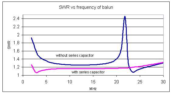
The SWR over the frequency range 1.8 MHz to 30 MHz is shown in the graph. (Figure 4) Performance with the series capacitor short-circuited (top curve) is greatly improved when the capacitor is in-circuit (lower curve). In service, the baluns have been very reliable. The only failures have been due to inadvertent transmitting into the balun with one leg of a vee antenna on the ground after storm damage, and to ingress of moisture. The moisture problem has been solved by liberally coating the join between the box and the lid, and also the type-N connectors, with flexible F2 adhesive.

Fig.3 Photo of the balun showing construction details

Fig. 4 Graph of the SWR versus frequency, measured at the 50 Ohm socket, with the 600 ohm terminals terminated by a non-inductivr 600 Ohm resistor
[1] L. A. Moxon "HF Antennas for All Locations", RSGB, 1986, p52
[2] J. Sevick "Transmission Line Transformers", ARRL, 1987, p 8-13.